=====================================================================================================
ISO 15765-4 CAN (250 Kbaud, 11 bit ID)
ISO 15765-4 CAN (500 Kbaud, 29 bit ID)
ISO 15765-4 CAN (500 Kbaud, 11 bit ID)
It works on a two-wire communication method (pin 6 and 14) and is the highest speed protocol which can handle data transfer speeds of up to 1 Mbps.
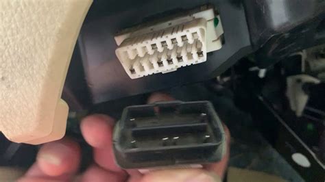
Cara Cek Protokol OBD2
OBD2 protocols: Must-have pins for the connector
Note: Pin 4 (chassis ground), Pin 5 (signal ground), and Pin 16 (power supply out) are included in all OBD2 protocols.
The easiest way to identify an OBD2 protocol is to look at the alignment and availability of the pins. Here's what you will need to focus on:
- If there are pins 2 dan 10 in the connector, with metallic pins 2, 4, 5, 10, and 16 then the vehicle is using the SAE J1850 PWM protocol.
- If you can see pin 2 dan material contacts inside pins 2, 4, 5, and 16 but there's no pin 10 then the vehicle is using the SAE J1850 VPW protocol.
- If the connector has pin 7 and maybe pin 15 then the vehicle could be using either the ISO 9141-2 or ISO 14230-4 (KWP2000) protocol. The metallic contacts will be inside pins 4, 5, 7, 15 (*optional), dan 16.
- If the vehicle has both pins 6 and 14 in its connector with material contacts 4, 5, 6, 14, and 16 then the vehicle is using the latest ISO 15765-4 (CAN) protocol.
Jenis Connector OBD2
As mentioned earlier in the article, there are two connector types, "Type A" dan "Type B".
Type A: This type of OBD2 connector has the standard 16 pins altogether, with 8 pins on the upper row and 8 pins on the bottom row. Between the top and bottom rows of pins, there is a solid or uninterrupted groove (single groove) which signifies that it is a Type A connector.
Type A connectors are generally found in light motor vehicles (cars) dan have a power output of 12V.
Type B: This OBD2 connector also has 16 pins (with 8 pins on the top and bottom rows) but it's a bit different from the Type A connector. The difference with the Type B connector is that it has a split groove in the center (double groove) which restricts the Type A male connector from connecting to a Type B female socket. However, you will still be able to plug a Type B male connector into a Type A female socket as the double groove male connector will fit into the single groove female socket.
Type B connectors are generally found in medium dan heavy duty vehicles dan have a power output of 24V.
Interpretasi Pin OBD2 Connector
Since we know that Type A dan Type B connectors both have 8 upper pins dan 8 lower pins, let's find out what each pin is meant for:
Pins on the upper row
- Pin 1: OEM COMM (Manufacturer specific).
- Pin 2: SAE J1850 Bus+.
- Pin 3: OEM Reserved/Discretionary (Manufacturer specific).
- Pin 4: Chassis ground.
- Pin 5: Signal ground.
- Pin 6: ISO 15765-4 (CAN High).
- Pin 7: K-Line.
- Pin 8: OEM Reserved/Discretionary (Manufacturer specific).
Pins on the lower row
- Pin 9: OEM COMM or Reserved/Discretionary (Manufacturer specific).
- Pin 10: SAE J1850 Bus- (SAE J1850 PWM only).
- Pin 11: OEM Reserved/Discretionary (Manufacturer specific).
- Pin 12: OEM Reserved/Discretionary (Manufacturer specific).
- Pin 13: OEM Reserved/Discretionary (Manufacturer specific).
- Pin 14: ISO 15765-4 (CAN Low).
- Pin 15: L-line.
- Pin 16: Power output (this pin powers the adapter).
Kesimpulan
We hope this information will help you identify your vehicle's OBD2 protocol. It can be a bit difficult since they all look very similar or the same, but you will get it if you pay attention to the design dan pins.
You may also like:
- Best OBD2 scanners (from cheap to expensive)
- OBD2: The Ultimate Guide