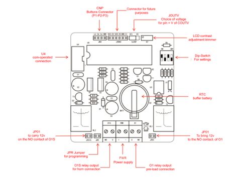
In this article, we will delve into the world of coin-operated devices, specifically focusing on timer coin slot diagrams. These diagrams are used to control and manage coin-operated mechanisms, ensuring accurate counting and timing. We will explore the basics of coin-operated devices, the importance of timer coin slot diagrams, and provide a comprehensive guide on how to create your own timer coin slot diagram.
What is a Timer Coin Slot Diagram?
A timer coin slot diagram is a visual representation of the electrical circuitry used in coin-operated devices. It provides a detailed illustration of the components, connections, and timing sequences involved in counting coins and operating mechanisms. These diagrams are essential for designing, building, and troubleshooting coin-operated systems.
Why Are Timer Coin Slot Diagrams Important?
Timer coin slot diagrams play a crucial role in ensuring accurate counting and timing of coins. They help:
- Accurate Counting: By accurately tracking the insertion and acceptance of coins, timer coin slot diagrams enable precise counting, eliminating errors and ensuring fairness.
- Timed Events: The diagrams control timed events, such as dispensing goods or services, providing a synchronized experience for users.
- Troubleshooting: When issues arise, timer coin slot diagrams facilitate troubleshooting by visualizing the electrical circuitry, making it easier to identify and resolve problems.
Creating Your Own Timer Coin Slot Diagram
To create your own timer coin slot diagram, follow these steps:
- Identify Components: Determine the components required for your specific coin-operated device, including coins, sensors, relays, timers, and power sources.
- Draw the Circuit: Sketch the electrical circuitry using a diagramming tool or software, such as Freepik, Katemangostar, Studiogstock, or Majnugraphics.
- Add Timing Sequences: Illustrate the timing sequences for coin insertion, acceptance, and rejection, including delays and time-outs.
- Label Components: Clearly label each component with its corresponding symbol (e.g., R for resistor) to ensure easy understanding of the circuit.
Real-World Examples
Let's take a look at some real-world examples:
- A vending machine using a power-relay-timer-vendo-kit, designed by Stephen Wenceslao.
- An arcade game incorporating a joystick-controlled servo, as described in an Arduino tutorial.
- A home automation system featuring a single LED relay oscillator circuit.
In this article, we have explored the world of timer coin slot diagrams and their importance in coin-operated devices. By understanding how to create these diagrams and incorporating them into your projects, you can ensure accurate counting and timing, as well as troubleshoot issues when they arise. Remember to consult resources like Freepik, Katemangostar, Studiogstock, or Majnugraphics for diagramming inspiration.
Resources
For more information on timer coin slot diagrams, visit the Circuitrocks Community (CIRCUITROCKS) and explore their tutorials on Arduino, ESP8266, ESP32, Raspberry Pi, and electronic modules.
