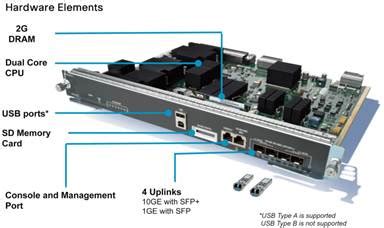
=====================================================
Langkah-Langkah Instalasi
Untuk menginstal switch 4500 series, ikuti langkah-langkah berikut:
Langkah 1: Persiapan untuk Menghindari Kerusakan ESD
Sebelum menginstal switch, pastikan Anda telah membaca dokumentasi Regulatory Compliance and Safety yang terkait dan telah mengambil tindakan untuk mencegah kerusakan ESD (Electrostatic Discharge).
Langkah 2: Pilih Slot untuk Switching Module
Pilih slot yang akan digunakan untuk switching module. Pastikan Anda memiliki cukup ruang untuk akomodasi peralatan interface yang akan dihubungkan ke port-port switching module. Jika möglich, tempatkan switching modules antara slot kosong yang hanya berisi filler plates switching-module.
Langkah 3: Lepas Scew Captive
Lepaskan screw captive yang mengikat plate filler switching-module (atau switch module sebelumnya) ke slot yang dipilih.
Langkah 4: Hapus Plate Filler atau Switch Module Sebelumnya
Hapus plate filler switching-module (atau switch module sebelumnya). Simpan plate filler untuk penggunaan masa depan. Jika Anda menghapus switch module sebelumnya, lihat bagian "Removing Switching Modules" di bawah ini.
Langkah 5: Instalasi Switching Module Baru
Grap the front panel of the new switching module with one hand, and place your other hand under the carrier to support the switching module. Pastikan Anda tidak menyentuh board printed circuit atau pin connector.
Langkah 6: Aliniasi Board dengan Slot Guides
Aliniasi edge of the circuit board with slot guides on the sides of the switch chassis, as shown in Figure 2.
Langkah 7-9: Pemasangan Switching Module
Pivot the two module ejector levers out and away from the faceplate. Carefully slide the switching module into the slot until the notches on both ejector levers engage with the chassis sides. Using the thumb and forefinger of each hand, simultaneously pivot in both ejector levers to fully seat the switching module in the backplane connector.
Peringatan
Selalu gunakan ejector levers saat menginstal atau menghapus switch module. Modul yang belum sepenuhnya ditempatkan dalam backplane tidak akan berfungsi dengan benar.
Langkah 10: Ketatkan Screw Captive
Gunakan screwdriver untuk ketatkan screw captive pada setiap ujung faceplate switching module.
Konfigurasi Status Switch Module
Untuk memeriksa status switch module, ikuti langkah-langkah berikut:
Langkah 1-3: Pastikan Status LED Hijau (Operasional)
Pastikan LED STATUS hijau. Ketika switch online, masukkan perintah "show module" dan verifikasi bahwa sistem mengakui modul baru dan status modul terdaftar sebagai baik dalam output perintah.
Langkah 4-5: Re-seat atau Kontak Customer Service
Jika modul tidak berfungsi, re-seatnya. Jika modul masih tidak berfungsi, hubungi representatif layanan pelanggan Anda.
Dokumentasi dan Pengajuan Service Request
Untuk informasi tentang mendapatkan dokumentasi, pengajuan service request, dan mengumpulkan informasi tambahan, lihat bulanan "What's New in Cisco Product Documentation" yang juga menampilkan semua dokumentasi teknis Cisco baru dan diperbarui, di: http://www.cisco.com/en/US/docs/general/whatsnew/whatsnew.html
Keterkaitan
Dokumen ini harus digunakan bersama-sama dengan dokumentasi yang mendukung perangkat Cisco Anda.
Tanda Merk
CCVP, the Cisco logo, and Welcome to the Human Network are trademarks of Cisco Systems, Inc.; Changing the Way We Work, Live, Play, and Learn is a service mark of Cisco Systems, Inc.; and Access Registrar, Aironet, BPX, Catalyst, CCDA, CCDP, CCIE, CCIP, CCNA, CCNP, CCSP, Cisco, the Cisco Certified Internetwork Expert logo, Cisco IOS, Cisco Press, Cisco Systems, Cisco Systems Capital, the Cisco Systems logo, Cisco Unity, Enterprise/Solver, EtherChannel, EtherFast, EtherSwitch, Fast Step, Follow Me Browsing, FormShare, GigaDrive, HomeLink, Internet Quotient, IOS, iPhone, IP/TV, iQ Expertise, iQ, and the iostat logo are trademarks of Cisco Systems, Inc.
