In a DC machine, understanding armature windings is crucial to grasp how they generate electricity. In this article, we will delve into pole pitch, coil span, and commutator pitch to shed light on the fundamentals of armature windings.
Pole Pitch
The pole pitch is defined as the peripheral distance between the centers of two adjacent poles in a DC machine. This distance is measured in terms of armature slots or armature conductors that come between two adjacent pole centers. In other words, it's the number of armature slots divided by the number of poles in the machine.
For example, if we have a 4-pole DC machine with 24 armature slots, the pole pitch would be:
Pole Pitch = Total Number of Armature Slots / Number of Poles
= 24 / 4
= 6
In electrical degrees, this would translate to:
Pole Pitch (electrical) = 180°
Coil Span And Commutator Pitch
The coil span refers to the distance between two adjacent slots occupied by an armature coil. In contrast, commutator pitch is defined as the distance between two commutator segments where two ends of the same armature coil are connected.
In a DC machine, the pole pitch, coil span, and commutator pitch work together to generate electricity. The pole pitch determines the number of coils that can be wrapped around each pole, while the coil span affects the amount of electromagnetic torque generated per pole. The commutator pitch, on the other hand, plays a crucial role in ensuring proper rotation of the armature.
Single-Layer And Two-Layer Armature Windings
There are two common types of armature windings: single-layer and double-layer windings.
In single-layer winding, each one side of an armature coil occupies a single slot. This means that each coil side is placed in a separate slot.
In contrast, double-layer winding involves placing two coil sides in every armature slot – one occupying the upper half and another the lower half. This configuration can increase the torque generated per pole while maintaining the same overall diameter as the armature.
Example: 4-Pole, 3-Phase, 24-Slots Double Layer Winding
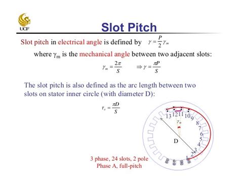
Consider the following figure for a 4-pole, 3-phase, 24-slots double layer winding. Find the pole pitch and the slot pitch angle:
Given data:
Number of slots = 24
Number of poles = 4
Pole Pitch Calculation:
Pole Pitch = Total Number of Armature Slots / Number of Poles
= 24 / 4
= 6
In electrical degrees, this would translate to:
Pole Pitch (electrical) = 180°
Slot Pitch Angle Calculation:
Slot pitch angle = πP / S
= π(4) / 24
= 30°
Armature windings play a vital role in generating electricity in DC machines. Understanding pole pitch, coil span, and commutator pitch can help designers optimize the performance of these devices. In this article, we explored the concepts and calculations involved in determining pole pitch and slot pitch angle for a 4-pole, 3-phase, 24-slots double layer winding.
References
- ST 1: UPRVUNL JE – Basic Concepts and Circuit law
- Uttar Pradesh Rajya Vidyut Utpadan Nigam Limited (UPRVUNL) Junior Engineer Recruitment Notification 2024
I hope this helps! Let me know if you have any questions or need further clarification.
